
How autonomous mobile robots use SLAM to determine their position
Many autonomous mobile robots use SLAM (Simultaneous Localization and Mapping) technology to determine their position and map their surroundings. Here is how this technology works, the hardware and software components it relies on, and its advantages and limitations.
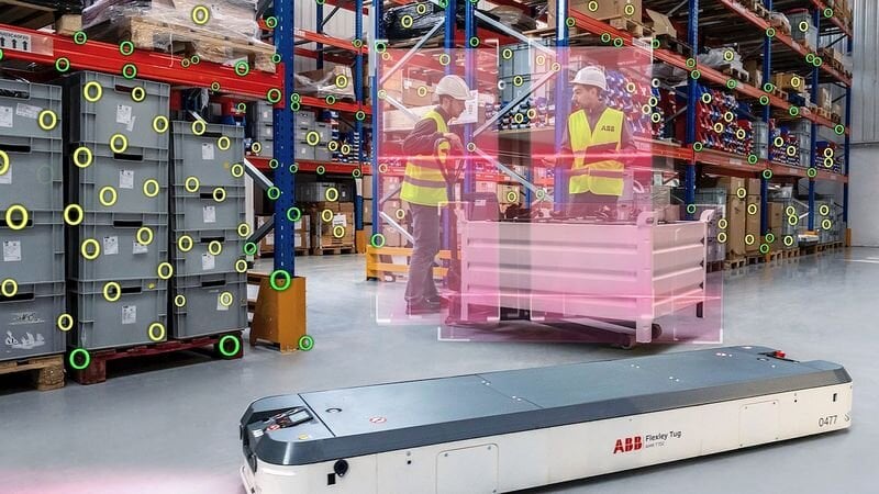
Autonomous mobile robots (AMRs) need to be able to operate in environments whose layout can change, with operators moving around, pallets being relocated, equipment positions changing or traffic areas being reconfigured. To navigate effectively, they must simultaneously determine their position and build a representation of their surroundings. This is precisely the role of SLAM (Simultaneous Localization and Mapping), a family of methods that enables a robot to perform both operations in parallel.
Unlike systems guided by rails, magnetic strips or markers installed on the floor, a SLAM system relies primarily on information provided by onboard sensors. The robot observes its surroundings, estimates its successive movements, identifies distinctive features and progressively updates a map. It can then use this map to determine its position and plan its movements.
The challenge of autonomous navigation
To move autonomously, a robot needs two pieces of information: where it is and how its surroundings are structured. The challenge becomes more complex when the robot does not initially have an accurate map of its environment.
SLAM addresses this problem by handling localisation and mapping simultaneously. As the robot moves, its sensors acquire data about its surroundings. The system uses these observations to estimate the robot's movement and determine the position of observed features. This information is used to build or complete a map, which in turn becomes a reference for subsequent position estimates.
There are several families of SLAM algorithms, designed for different types of sensors and environments. SLAM therefore does not refer to a single sensor or algorithm, but to a class of localisation and mapping methods.
The main sensors required for a SLAM system
A SLAM system generally combines several sources of information. The choice depends on the type of robot, its operating environment and the required level of accuracy.
LiDAR (Light Detection and Ranging) is widely used on industrial AMRs. It emits laser pulses and measures their return time to estimate the distance to obstacles. A 2D LiDAR provides a cross-section of the environment in a horizontal plane, while a 3D LiDAR generates a point cloud that can represent structures in three dimensions.
Cameras can also provide the information required for SLAM. In a visual SLAM system, successive images are analysed to identify visual features and track their movement. A stereo camera or a system equipped with several cameras can also provide information for estimating depth.
Inertial measurement units, or IMUs, use accelerometers and gyroscopes to measure the robot's acceleration and angular velocity. They help estimate rapid robot movements and are particularly useful when visual or LiDAR observations are temporarily insufficient.
Finally, wheel encoders provide an estimate of the robot's movement based on wheel rotation. This technique, known as odometry, is straightforward to implement and provides continuous information about motion. However, it is subject to drift: slight wheel slippage or a measurement error will eventually create a discrepancy between the calculated position and the robot's actual position.
In industrial systems, these different sources can be fused. LiDAR or cameras provide observations of the surroundings, while odometry and the IMU provide information about the robot's motion.
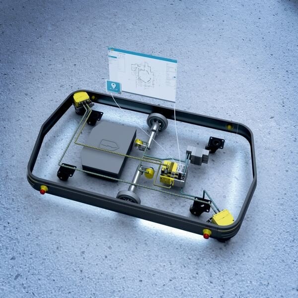
Sick offers a range of sensors and software solutions for the navigation, localisation and positioning of mobile robots.
How SLAM works
The process can be broken down into several operations that are performed iteratively as the robot moves.
1. Data acquisition
The onboard sensors observe the surroundings at regular intervals. A LiDAR, for example, can provide a series of distance measurements corresponding to walls, racking, machines or other obstacles. A camera, meanwhile, provides successive images.
At the same time, the system receives odometry data and, depending on its architecture, measurements from the IMU.
2. Motion estimation
Using two successive observations, the algorithm attempts to determine how the robot has moved.
With LiDAR, it can compare two scans and determine the geometric transformation required to match the two sets of points. With a camera, it can track distinctive features appearing in several images and estimate the corresponding motion.
This estimate forms the system's odometry. However, errors can accumulate as the robot moves.
3. Identifying features in the environment
The system must then identify elements that can serve as reference points. Depending on the technology used, these may be points or surfaces detected by LiDAR, visual features identified in images, or geometric structures such as walls and corners. Repeated observations of these features enable the system to relate the robot's different positions to the same environment.
4. Building the map
The observations are incorporated into a digital representation of the environment. In a warehouse, for example, this may be an occupancy grid in which each cell indicates whether an area is considered free, occupied or unknown.
Other representations are also possible, including maps based on geometric features or 3D representations in the form of point clouds.
The map is therefore not necessarily an image in the conventional sense. It is a data structure used by localisation and navigation algorithms.
5. Alignment and trajectory correction
A significant problem arises when odometry errors accumulate. If the robot travels for a long period without correcting its estimate, its calculated position may gradually diverge from its actual position.
SLAM addresses this by using repeated observations of the environment. When a previously observed feature is detected again, the system can recognise that it has returned to a known area. This detection, known as loop closure, makes it possible to correct errors that have accumulated in both the trajectory and the map.
Optimisation algorithms are then used to adjust the estimated positions of the robot and the features on the map simultaneously. Modern SLAM systems can, for example, represent the problem as a pose graph, in which nodes correspond to the robot's different positions and constraints represent observations or movements between these positions.
Localisation and navigation: two different functions
It is important to distinguish SLAM from the AMR's overall navigation system. SLAM provides an estimate of the robot's position and a representation of its surroundings. The navigation system then uses this information to determine how to reach a destination.
A complete architecture can therefore include a localisation layer, a global planning layer and a local planning layer. The global planner calculates a route between the current position and the destination using the map. The local planner then adapts the trajectory to obstacles detected in real time.
The robot can therefore follow an overall route while modifying it whenever an operator, trolley or pallet appears in its path.
Advantages over traditional guidance systems
The main advantage of SLAM is that it does not necessarily depend on guidance infrastructure installed on the floor or elsewhere in the environment.
With wire guidance, a cable installed in the floor generates a field that is detected by the robot. With magnetic tape, the route is physically marked out on the floor. Systems using markers, reflectors or beacons likewise provide the robot with fixed reference points.
These solutions can be effective in environments where material flows and routes are relatively stable. However, any change to a route may require modifications to the infrastructure.
With SLAM, the map is essentially defined by the digital data acquired by the robot. Changes to the environment can therefore be incorporated into the system without necessarily modifying the floor or installing new guidance equipment.
In some architectures, SLAM also enables several robots to share a digital representation of their surroundings. Fleet management systems can then assign missions and coordinate movements while using localisation information supplied by the robots.
However, this software flexibility should not be confused with a robot's actual ability to operate in any environment: navigation performance remains directly dependent on the sensors, algorithms and characteristics of the site.
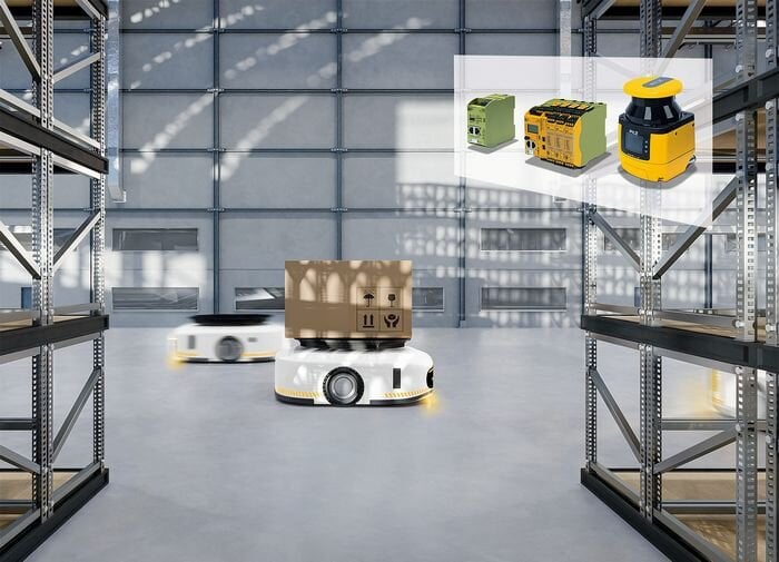
Pilz offers safety laser scanners, modular safety relays, as well as control and signalling devices designed to ensure the safe movement of AMRs.
The limitations of SLAM
SLAM does not eliminate the challenges associated with perceiving the environment. Instead, it largely shifts them to the sensors and data processing systems.
One challenge concerns environments with few distinctive features. A long uniform wall, a highly reflective surface or an area with little visual detail can make it difficult to identify reliable reference points. Systems relying primarily on vision can encounter particular difficulties in poorly lit areas or environments whose appearance changes significantly.
Moving objects pose another challenge. A person, trolley or moving pallet may be interpreted as a change in the environment even though it is not a fixed feature of the map. Algorithms must therefore distinguish static structures from moving objects as effectively as possible.
Localisation drift also remains a fundamental issue. Even when a system is equipped with LiDAR or a camera, measurement and estimation errors accumulate when observations are insufficient. Loop-closure mechanisms can limit this drift, but their effectiveness depends on the system's ability to correctly recognise an area that has already been mapped.
Environmental conditions can also affect sensors. Dust, steam, transparent or reflective surfaces and certain geometric configurations can interfere with LiDAR measurements. For vision-based systems, lighting, shadows and changes in appearance can have a comparable effect.
Deployment constraints to consider
Deploying a SLAM-based AMR generally begins with mapping the site. The robot must travel through the environment to acquire the data required to build its map.
The quality of this map depends in particular on the building layout, the visibility of fixed structures and the accuracy of the sensors. Accessible areas, restricted areas, traffic routes and any priority rules governing interactions between robots and other equipment must also be defined.
Computing capacity is another constraint that must be considered. Data from one or more LiDARs, cameras and inertial sensors must be processed with sufficiently low latency to allow the robot to react while moving. Increasing the number of sensors or using 3D data generally increases computing and storage requirements.
Finally, SLAM is only one component of an AMR's safety architecture. Detecting an obstacle and taking it into account when determining the trajectory are navigation and safety functions that must be designed and validated separately. In an industrial environment, the system must in particular take into account the coexistence of operators and other mobile equipment.
SLAM as a building block for autonomous navigation
SLAM therefore provides a solution to the fundamental challenge of navigating through an unknown or changing environment: simultaneously estimating the robot's position and the structure of its surroundings. To achieve this, it combines sensors, odometry, perception and optimisation algorithms, and a digital representation of the space.
Compared with guidance systems based on fixed infrastructure, its main advantage lies in the ability to build and use a digital map without imposing a physically defined route on the robot. This makes it easier to adapt routes when the layout of a site changes.
A SLAM system nevertheless remains dependent on the quality of the available observations and the algorithms' ability to distinguish fixed features from moving objects. Sensor selection and positioning, available computing power and site preparation are therefore just as important as the SLAM algorithm itself. For an industrial AMR, autonomous navigation consequently results from the integration of several building blocks — perception, localisation, mapping, planning and safety — rather than from a single technology.
Published by Youssef Belgnaoui, editor at Induportals.
